

Meshing
Express Mesh Component
Generate surface meshes from CAD BRep shapes with Express Mesh. Control element size and deflection for visualization and downstream processing.
On this page
Surface meshing from CAD BRep geometry
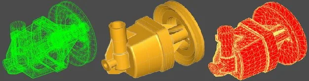
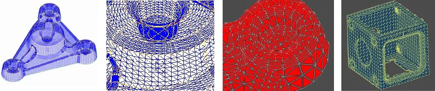
Express Mesh generates triangular and quadrangular surface meshes from OCCT faces, shells, solids and compounds of faces. It provides control over element size, chordal deflection and angular deviation for applications that need to balance geometric detail and mesh size.
CAD tessellation is part of many visualization and exchange pipelines. For a STEP, Parasolid or ACIS model, import the geometry first, then select the surface mesh settings needed by the next operation. See the CAD format and conversion matrix.
Control mesh quality and size
- Select triangular or quadrangular elements for the required workflow.
- Set minimum and maximum element sizes to control local detail and large flat regions.
- Set chordal deflection to control deviation from the CAD surface.
- Set angular deviation to control discretization on curved areas.
- Evaluate connectivity across shared face boundaries and processing behavior on difficult input geometry.
The component includes edge and wire processing and parallel computation options. Surface meshing should be distinguished from a volume mesh for finite-element analysis; establish the downstream solver’s requirements separately.
Meshing parameters in detail
| Parameter | Effect on the generated surface mesh |
|---|---|
| Element type | Select triangular or quadrangular elements |
| Minimum element size | Set the lower size limit for element sides and the scale of retained detail |
| Maximum element size | Limit large elements on flat regions and elongated elements on cylindrical surfaces |
| Chordal deflection | Control the deviation between mesh elements and the original CAD surface |
| Angular deviation | Control the deviation between element normals and surface normals on curved regions |
The component includes a shape-measurement system that suggests meshing parameters from the input geometry. These suggestions provide a starting configuration that can be adjusted for visualization, collision analysis or downstream simulation preparation.
Edge discretization, wire repair and shared boundaries
Express Mesh coordinates discretization on connected faces so that their meshes connect across shared edges. This matters when downstream processing needs a connected surface instead of separate face tessellations.
Its preparation operations include:
- Creating well-spaced discrete edge segments even when the underlying curves are poorly parameterized.
- Detecting and resolving self-intersections in discrete curves, including removal of small loops.
- Connecting adjacent discrete curves into closed contours.
- Detecting and resolving intersections between wires on a face.
Sequential and parallel computation modes are available. The SDK operates on OCCT BRep shapes; its accompanying documentation describes configuration and operational limits for the corresponding OCCT delivery.
Evaluate CAD tessellation performance
Use the same source geometry, tolerance settings, hardware and output requirements when comparing meshers. Record elapsed time, memory, element count, geometric deviation and connectivity. A faster result with less detail is not an equivalent-quality comparison.
Check representative small parts and large assemblies, plus the imperfect geometry found in your actual import pipeline. For a closed mesh around dirty tessellation, compare Surface Wrapping. For mesh data integration in a CAE application, see Mesh Framework.
Discuss Express Mesh evaluation with your OCCT version, input formats, target element type and performance requirements. OCCT consulting can help scope profiling and integration work.